Snap-Lock Metal Roofing Panel Installation Guide

S3 Metals Snap-Lock panels deliver the clean appearance and concealed-fastener performance of standing seam roofing with a simplified snap-together installation system. Available in 1" and 1½" profiles, Snap-Lock panels are designed for residential, commercial, agricultural, and architectural roofing applications.

Introduction

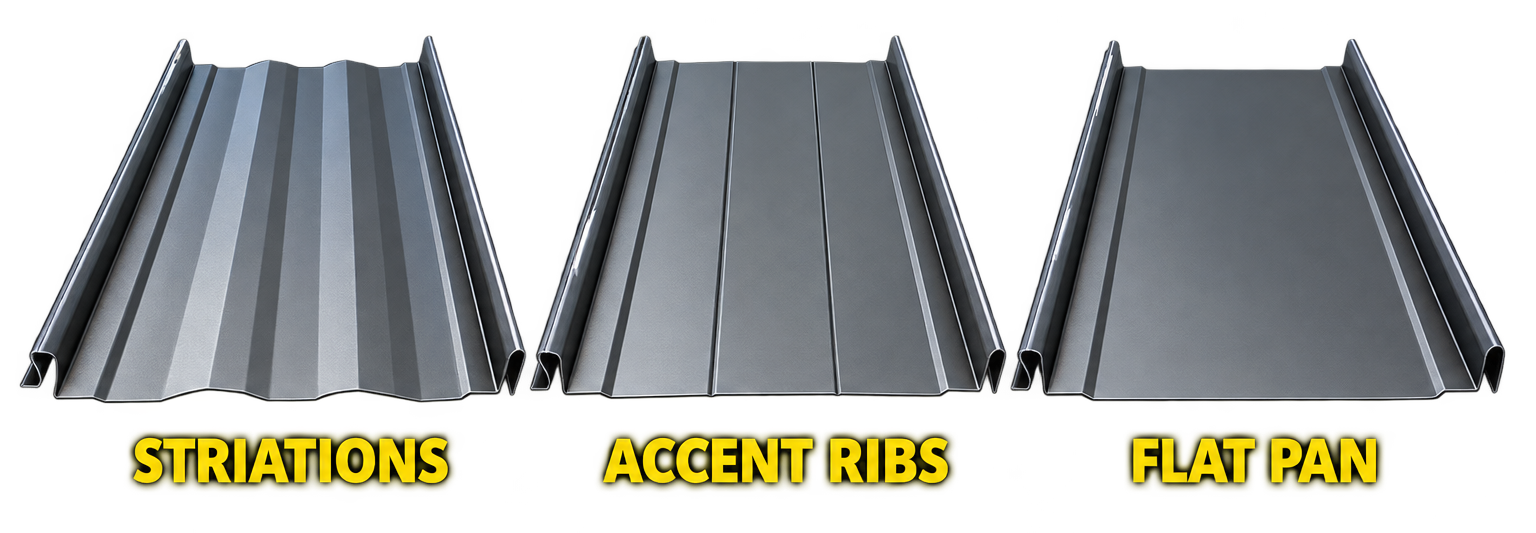
snap lock panel types

S3 Metals™ Snap-Lock standing seam roofing systems are engineered for residential, commercial, agricultural, and architectural applications. Designed for long-term performance, the concealed fastener system provides a durable, weather-tight, and visually appealing roofing solution while allowing for efficient installation and thermal movement. This Installation Guide outlines recommended practices for common roof configurations and construction methods; however, project conditions, building designs, and local code requirements vary. These instructions are intended as general guidance and may not address every application, detail, or field condition. Additional flashing details, project-specific recommendations, and technical assistance are available from S3 Metals upon request.


It is the responsibility of the installer, contractor, architect, engineer, and building owner to ensure compliance with all applicable building codes, engineering requirements, safety regulations, and industry best practices. S3 Metals supplies materials only and does not provide installation, supervision, engineering, or construction services. All measurements, field verification, design criteria, and installation methods remain the responsibility of the buyer and/or installer. S3 Metals assumes no liability for installation errors, field measurement inaccuracies, improper use of materials, code compliance issues, personal injury, property damage, or consequential damages arising from the handling, installation, or use of its products.


David Hahne - Owner and Operator

DELIVERY & LOGISTICS

  • Handling Details for Snap-Lock Panels

    Handle all panels, trim, flashings, and accessories with care during unloading, transportation, and installation to prevent damage.


    Long panels may require multiple lift points spaced evenly along the panel length to avoid bending, twisting, or permanent deformation. Contact S3 Metals for recommendations regarding handling, lifting, and transporting long-length panels.


    When handling painted panels, aluminum, copper, or Zincalume® products, use clean gloves to minimize fingerprints, oils, and surface contamination. While fingerprints typically do not affect product performance, they may temporarily impact appearance until natural weathering occurs.


    Wear clean, soft-soled footwear when walking on installed roofing panels. Dirt, gravel, metal shavings, and other debris attached to footwear can scratch painted surfaces and damage protective coatings. Avoid walking on panel ribs whenever possible, and never walk on panels that have not been fully secured according to installation requirements.


    Exercise caution when painting near installed roofing materials. Paint overspray may permanently affect the appearance and performance of coated metal surfaces, and wind can carry paint particles significant distances beyond the immediate work area.


    Metal panels should not come into direct contact with pressure-treated lumber or other chemically treated materials that may cause corrosion. Use approved separation materials, such as self-adhered underlayment or membrane barriers, when contact cannot be avoided.

  • Storage Details for Snap-Lock Panels

    Store all panels, flashings, and accessories in a dry, well-ventilated location on level ground. Bundles should be elevated off the ground and adequately supported to prevent sagging, distortion, or water accumulation. Slightly elevate one end of stored bundles to promote drainage.


    If materials must be covered, ensure adequate airflow around and beneath the bundles to prevent moisture buildup and condensation. Standing water trapped between panels can cause staining, finish damage, and premature corrosion.


    If materials become wet during storage or transportation, separate individual panels immediately, wipe them dry with a clean cloth, and allow them to air dry completely before restacking.


    Protective plastic film applied to panels, trim, or flat sheets must be removed prior to installation. Materials with protective film should not be stored in direct sunlight, exposed to UV sources, or subjected to extreme temperatures for extended periods, as prolonged exposure may make film removal difficult.


    Secure all materials stored on the ground or roof to prevent movement caused by wind. Unsecured materials may result in product damage, property damage, or personal injury.

  • Safety Statement

    Avoid installing roofing materials during high-wind conditions. Safe handling, installation procedures, and jobsite safety remain the sole responsibility of the installer.


    Always follow applicable OSHA requirements, local safety regulations, and accepted industry practices. Use appropriate fall protection, personal protective equipment, gloves, eye protection, and other safety equipment necessary to reduce the risk of injury during handling and installation.

  • Customer Responsibilities

    • Verify adequate site access before scheduling delivery.
    • Be present or have an authorized representative available at the time of delivery.
    • Provide unloading assistance, equipment, or labor as required.
    • Inspect all materials upon delivery.
    • Verify quantities against the packing list.
    • Report any shortages, damage, or discrepancies within 48 hours.
  • Delivery Information

    • Delivery schedules are typically confirmed one business day in advance.
    • S3 Metals will make every reasonable effort to deliver materials on time.
    • Delays caused by weather, traffic, road closures, equipment issues, or other factors beyond our control may occur.
    • Customers will be notified of significant delays whenever possible.
  • Site Access Requirements

    • Delivery locations must be reasonably accessible and safe.
    • Narrow roads, steep grades, tight turns, overhead obstructions, or unsafe site conditions may prevent direct delivery.
    • If necessary, materials may be delivered to an alternate location approved by the customer.
    • Additional delivery charges may apply for special accommodations, return trips, or failed delivery attempts.
  • Material Responsibility

    • Upon delivery or release of materials, responsibility transfers to the buyer.
    • Materials should be inspected, secured, and stored in accordance with S3 Metals handling and storage guidelines.

ROOF PREPARATION

Click each section to reveal the step by step process and related diagrams

  • Installation Tools

    • Variable-speed screw gun with adjustable clutch
    • Extra batteries and charger
    • Magnetic bit holder
    • #2 Square Drive or Phillips bits
    • 1/4" Magnetic Hex Driver
    • 1/8" Drill Bit
    • Tape Measure
    • Chalk Line
    • Marking Pen or Grease Pencil
    • Rivet Tool
  • Storage Details for Snap-Lock Panels

    Store all panels, flashings, and accessories in a dry, well-ventilated location on level ground. Bundles should be elevated off the ground and adequately supported to prevent sagging, distortion, or water accumulation. Slightly elevate one end of stored bundles to promote drainage.


    If materials must be covered, ensure adequate airflow around and beneath the bundles to prevent moisture buildup and condensation. Standing water trapped between panels can cause staining, finish damage, and premature corrosion.


    If materials become wet during storage or transportation, separate individual panels immediately, wipe them dry with a clean cloth, and allow them to air dry completely before restacking.


    Protective plastic film applied to panels, trim, or flat sheets must be removed prior to installation. Materials with protective film should not be stored in direct sunlight, exposed to UV sources, or subjected to extreme temperatures for extended periods, as prolonged exposure may make film removal difficult.


    Secure all materials stored on the ground or roof to prevent movement caused by wind. Unsecured materials may result in product damage, property damage, or personal injury.

  • Cutting Tools

    • Left and Right Offset Snips
    • Left and Right Aviation Snips
    • Electric Shears — recommended for long cuts
  • Additional Tools

    • Deburring Tool
    • Hole Punch
    • Rubber Mallet
    • Framing Square or Speed Square
    • Duckbill Pliers or Vise Grips
    • Panel Upender Tools
    • Tool Belt or Holster
  • Safety Equipment

    • Safety Harness and Fall Protection Equipment
    • Safety Glasses
    • Work Gloves
    • Hearing Protection
    • Soft-Soled Work Boots
    • Cotton Gloves when handling Copper or Zincalume®
  • Site Access Requirements

    • Delivery locations must be reasonably accessible and safe.
    • Narrow roads, steep grades, tight turns, overhead obstructions, or unsafe site conditions may prevent direct delivery.
    • If necessary, materials may be delivered to an alternate location approved by the customer.
    • Additional delivery charges may apply for special accommodations, return trips, or failed delivery attempts.
  • Material Responsibility

    • Upon delivery or release of materials, responsibility transfers to the buyer.
    • Materials should be inspected, secured, and stored in accordance with S3 Metals handling and storage guidelines.
  • New Construction for Snap-Lock Panels

    S3 Metals Snap-Lock roofing systems are designed for installation over a solid, continuous roof deck. A minimum 1/2" plywood or OSB substrate is recommended.


    Roof decking should be flat, secure, dry, and free of debris before installation begins. Install an approved roofing underlayment over the entire roof surface in accordance with local building codes and manufacturer specifications.


    Follow all underlayment overlap and fastening requirements to ensure proper moisture protection.

  • Re-Roof Applications

    Snap-Lock panels may be installed over a single layer of existing asphalt composition roofing where permitted by local building codes and where the existing roof surface is flat, secure, and in good condition.

  • Before Installation

    • Inspect the roof deck for damage, rot, or structural deficiencies.
    • Repair or replace damaged sheathing as necessary.
    • Remove loose materials, protruding fasteners, moss, and debris.
    • Verify compliance with local code requirements regarding roof overlays.
  • Roof Surface Considerations

    • Uneven substrates may affect panel appearance and alignment.
    • Secure any loose roofing materials before installation.
    • Remove conditions that may interfere with proper panel installation.
    • Ensure all fastening surfaces are structurally sound.
  • Ventilation

    • Proper attic and roof ventilation are critical to long-term roof performance.
    • Follow all local building code ventilation requirements.
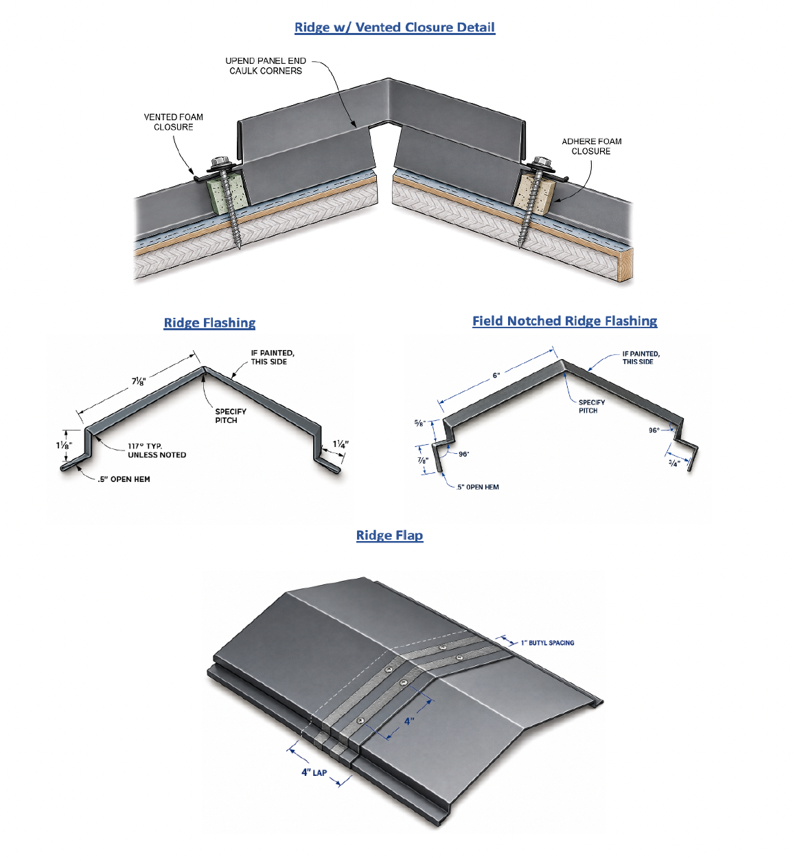
    • Ridge ventilation openings should be installed where applicable.
    • Use approved vent materials and insect screening.
    • Provide adequate airflow between insulation and roof decking.
    • Insufficient ventilation can contribute to moisture buildup, reduced roof life, and premature deterioration of materials.
  • Insulation

    Insulation design should comply with local building codes and project-specific energy requirements. Consult the project’s architect, engineer, or insulation professional when determining insulation specifications.

  • Touch-Up Paint

    Minor scratches and handling marks should be repaired using manufacturer-approved touch-up paint.


    • Apply paint only to the affected area.
    • Use a fine brush or applicator rather than spraying directly onto the panel.
    • Excessive touch-up paint may create visible color variations over time.
    • Touch-up paint is intended for minor repairs and should not be used to repaint large panel surfaces.

RECOMMENDED FASTENERS

Recommended Fastenters

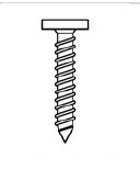
  • Pancake Head Screw

    #10 x 1" Pancake Head Screw


    Used for concealed clip attachment and panel fastening. Recommended where the fastener will not be exposed after installation.

  • Wafer Head Screw

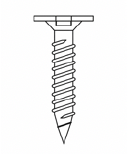
    #9 Wafer Head Screw, Sharp Point


    Used for attaching clips and concealed roofing components to wood decking or structural substrates. Provides increased holding strength compared to pancake head screws.

  • Title or Question

    Describe the item or answer the question so that site visitors who are interested get more information. You can emphasize this text with bullets, italics or bold, and add links.
TRIANGLE METHOD DETAILS & DIAGRAMS

  • Step 1

    roof layout step 1

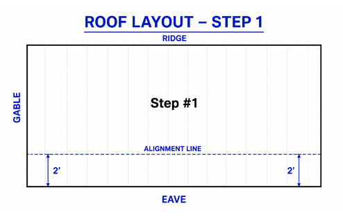
    Snap a chalk line parallel to the eave approximately 24 inches from the roof edge. This line will serve as your baseline reference.

  • Step 2

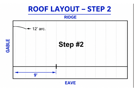
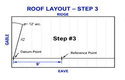
    Select a datum point on the alignment line near the gable edge. From this point, create a 12-foot arc extending toward the ridge.

  • Step 3

    step 3 roof layout

    Measure 9 feet along the alignment line from the datum point and mark a reference point. 

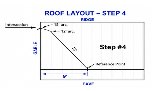
  • Step 4

    step 4 roof layou

    From the reference point, create a 15-foot arc until it intersects the 12-foot arc. Snap a chalk line from the datum point through the arc intersection. This establishes a square alignment line for the first panel.

  • Step 5

    Where valleys are present, establish valley centerlines before panel installation. Since underlayment may conceal these locations, clearly mark valley alignment lines to ensure proper placement of valley flashing and adjacent panels.

  • IMPORTANT / CAUTION:

    The first panel controls the alignment of the entire roof system. Verify all measurements befoe installation. Even minor alignment errors at the starting point can compound across the roof and affect panel appearance, flashing fitment, and overall installation quality.

SNAP-LOCK FRAMING SQUARE DETAILS & DIAGRAMS

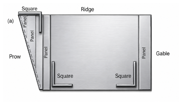
  • Introduction to Gable vs Prow Roof

    square diagrams

    The framing square method is a quick and effective way to establish a straight starting point for panel installation. Begin by

    establishing a straight reference line along the eave. After eave flashing has been installed, position the first panel and use a

    framing square to verify the panel is square to the eave and alignment line.


    Once properly aligned, secure the panel with temporary fasteners at the top and bottom. Install the next panel and verify

    alignment before proceeding with the remainder of the roof.

  • Gable Roofs

    Verify the first panel remains square to the eave. Check the distance between the panel edge and gable edge throughout the roof length. Minor variations can typically be accommodated by gable trim. Significant out-of-square conditions may require ripping the first or last panel to maintain a straight appearance.


    In situations where the roof is substantially out of square, custom trim or alternative flashing details may be required.

  • Prow Roofs

    Prow roofs require additional layout attention due to the angled roof geometry. Establish the centerline and verify all dimensions before panel installation.


    Install the first panel using a verified reference line. Confirm alignment at both the eave and prow before installing additional panels. Panels may require field trimming to maintain consistent panel spacing and visual alignment.


    The accuracy of the first panel is critical, as any alignment error will be amplified across the roof surface.

  • Panel Alignment Verification

    Before installing full-length panels, verify panel alignment at the eave, confirm panel spacing is consistent, check that the panel remains square to the established reference line, and make adjustments early to avoid cumulative alignment issues.


    When properly aligned, the first full-length panel will establish the reference for the remainder of the roof system.

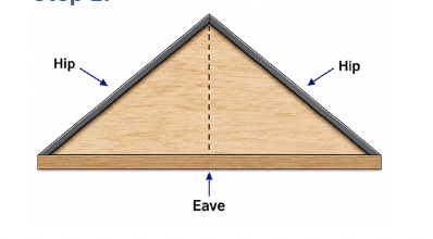
  • Hip Roofs

    Hip roofs present unique alignment challenges and require careful planning before installation. Establish the centerline of the roof and install a reversing strip or center reference point. Begin installation from the center and work outward in both directions while continuously verifying panel spacing and alignment.


    An alternative method is to begin with a longer panel positioned near the center of the roof area. Verify alignment using either the 3-4-5 Triangle Method or Framing Square Method. Install the remaining panels working back toward the shorter roof sections.

SNAP-LOCK REVERSING STRIP DETAILS & DIAGRAMS

  • Snap Lock Reversing Strip Intro

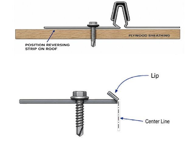
    reversing diagram

    The S3 Metals Reversing Strip allows Snap-Lock panels to be installed in opposing directions from a common centerline. This method is most commonly used on hip roof applications to maintain panel balance and alignment, but it may also be used on other roof configurations where installation from a center reference point is preferred.

  • Step 1

    reversing step 1 snap lock

    Locate and mark the centerline of the roof section using either the 3-4-5 Triangle Method or the Framing Square Method.


    Snap a straight chalk line perpendicular to the eave. The accuracy of this line is critical, as it will serve as the reference point for aligning the panels on both sides.


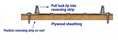
    Position the reversing strip along the centerline and fasten it securely to the roof deck using approved wafer head fasteners spaced 18" to 24" on center.

  • Step 2

    reversing strip step 2

    Position the first panel so the female locking rib engages the lip of the reversing strip.


    Pull the panel firmly into position and fasten the panel according to S3 Metals installation requirements.


    Verify alignment before proceeding with additional panels.

  • Step 3

    reversing strip step 3

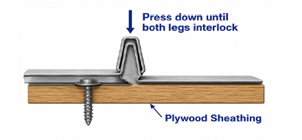
    Install the next panel in the opposite direction, engaging the female locking rib over the corresponding rib of the previously installed panel.


    Apply firm downward pressure until the panel is fully seated and locked into position. Secure the panel using the recommended fastening method.


    Continue installation outward from the centerline while periodically checking panel alignment.

  • IMPORTANT INFO:

    The reversing strip allows installers to work from the center of the roof toward both edges, helping maintain balanced panel layout and reducing alignment issues on complex roof designs.

  • CAUTION / WARNING:

    Before using a reversing strip, verify that all panels, accessories, and flashing details are compatible with this installation method. Improper use may affect panel fitment, appearance, and overall system performance.

PANEL PREPARATION

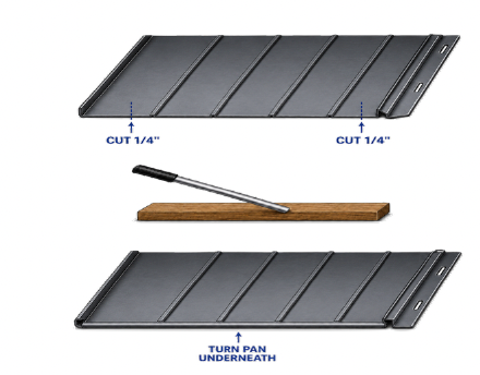
  • Top of Panel – Upend

    panel prep step 1

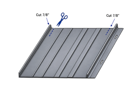
    At the top of each panel, create the required relief cuts at both panel edges as shown in the applicable detail drawings. After making the cuts, use an approved bending tool to turn the panel pan upward slightly beyond 90 degrees.


    The upended section acts as a water stop, helping prevent moisture intrusion at the upper termination of the panel system. Seal all exposed openings created by the upend process with an approved sealant to maintain a weather-tight assembly.

  • Bottom of Panel

    panel prep step 2

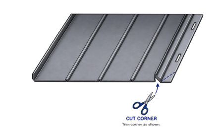
    At the eave end of the panel, trim the corner of the fastening flange as shown in the detail drawings. This trim improves appearance and allows proper fitment of adjacent trim and flashing components.

  • Low-Slope Applications

    low slope applicati

    For roof slopes below 3:12, additional panel preparation may be required to improve water management at the eave.

  • Option 1 – Open Hem

    Using an approved bending tool, form an open hem by bending the panel pan downward and back underneath itself at the eave end. This detail helps reduce the potential for water wicking or siphoning beneath the panel. When using this method, allow additional panel length as required to accommodate the hem detail.

  • Option 2 – Drip Edge Bend

    As an alternative, a slight downward bend may be formed at the eave end of the panel to create a drip edge. This detail encourages water to shed cleanly away from the panel edge and eave flashing.

  • IMPORTANT INFO:

    S3 Metals recommends a minimum roof slope of 3:12 for Snap-Lock panel systems. Projects with roof slopes below 3:12 should be reviewed prior to fabrication to ensure appropriate panel preparation, flashing details, sealant requirements, and installation methods are incorporated into the design.
PANEL INSTALLATION

  • Prior to Panel Installation

    Before installing panels, verify that all required roof preparation has been completed. This includes installation of the approved underlayment, eave flashing, valley flashing, gable flashing, and any other trim or flashing components required for the specific roof design.

  • Before ordering or installing panels:

    Carefully verify all roof dimensions. Roofs are rarely perfectly square, and minor dimensional differences from one end of the roof to the other are common.


    Proper layout planning before installation can help minimize narrow panel conditions and improve the overall appearance of the finished roof.


    When working on roofs that are out of square:


    Consider adjusting panel layout, panel widths, or flashing details to maintain a balanced and professional appearance across the roof system.


    Inspect all panels and accessories prior to installation. If any material appears damaged, defective, or incorrect, stop installation immediately and contact S3 Metals.


    Installing damaged or defective materials may affect roof performance and may limit warranty coverage. S3 Metals must be given the opportunity to review and resolve any material concerns before replacement materials are provided.

  • First Panel Installation

    Panels may be installed from left to right or right to left depending on project conditions and installer preference.


    Determine the installation direction before preparing or installing the first panel.


    Align the first panel with the established layout line at the gable edge. Position the panel to provide the required eave overhang specified in the applicable flashing details.


    Apply sealant where required by the flashing detail and fasten the panel according to S3 Metals installation requirements. Verify the panel is square and properly aligned before proceeding.

  • Second and Successive Panels

    Apply sealant where required by the applicable flashing detail.


    Position the female rib of the next panel over the male rib of the previously installed panel. Engage the locking ribs and apply firm, even pressure until the panel is fully seated and locked into position.


    Panels may be locked using hand pressure, foot pressure, or a non-marring rubber mallet as necessary. Always work from the eave toward the ridge while verifying proper engagement of the locking ribs.


    Once the panel is fully seated and aligned, install the required fasteners. Continue this process for each successive panel, periodically checking panel alignment and roof layout to ensure a straight, consistent installation.


    Proper alignment of the first panel is critical. Small alignment errors at the beginning of installation can become magnified as additional panels are installed across the roof.

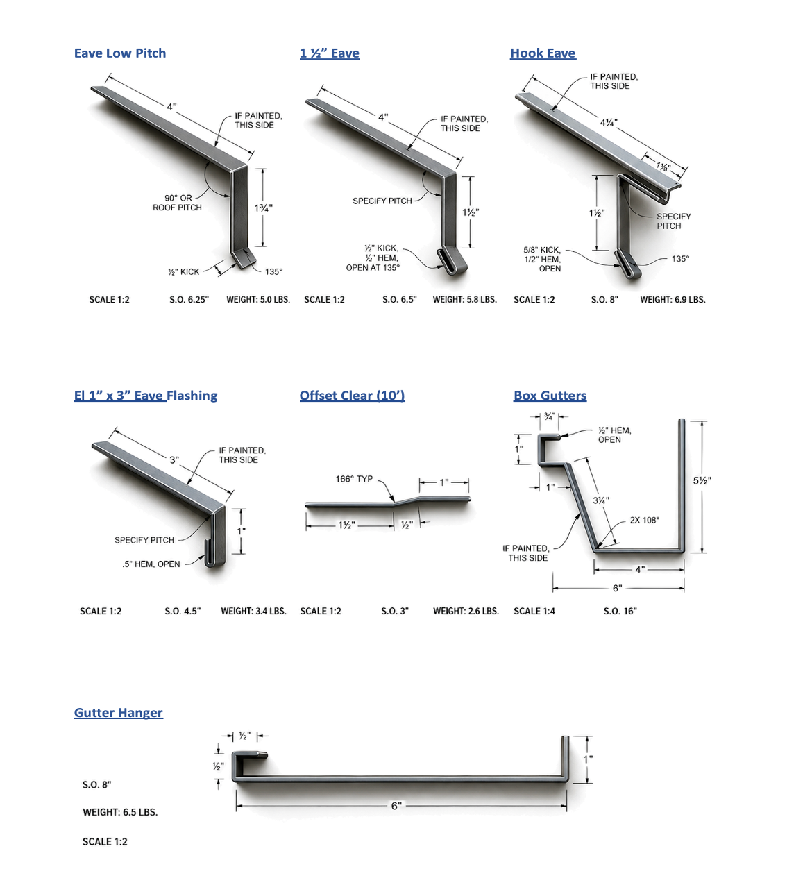
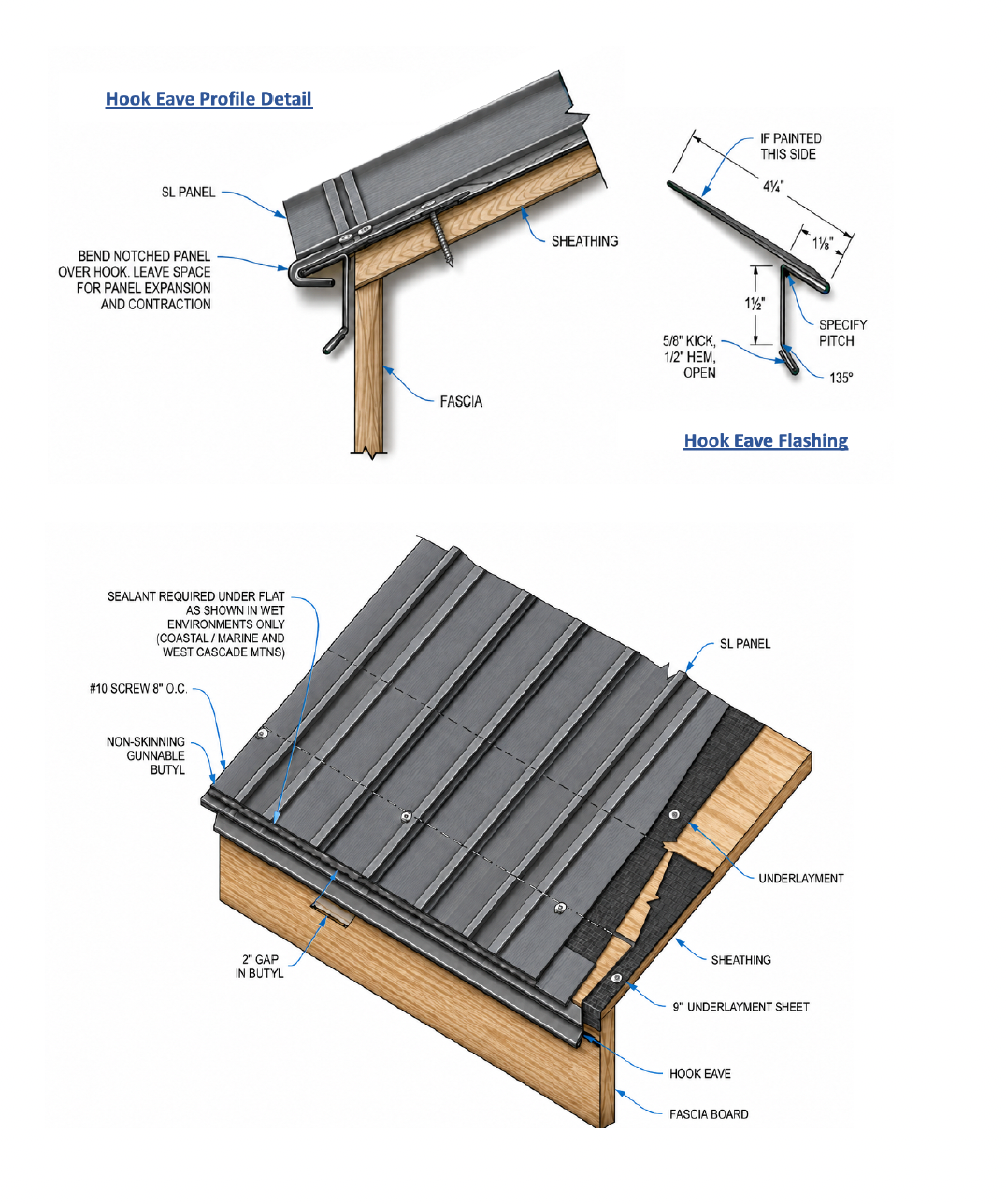
HOOK EAVE DETAILS & DIAGRAMS

hook eave diagram

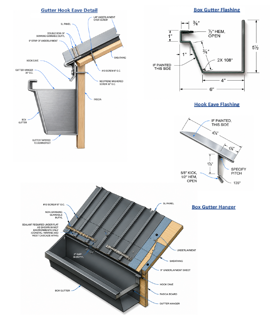
HOOK EAVE WITH GUTTER DETAILS & DIAGRAM

hook eave with gutters diagram

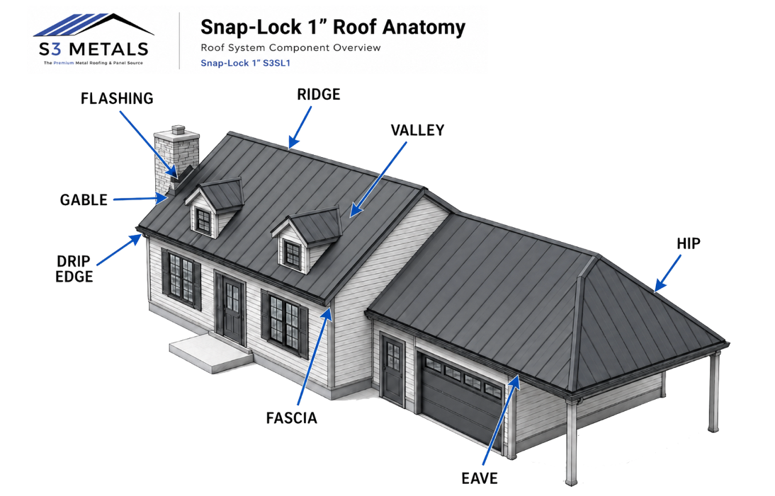
HIP / RIDGE DETAILS & DIAGRAMS

hip ridge diagram
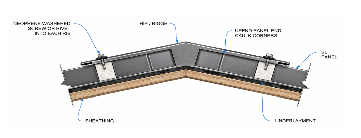
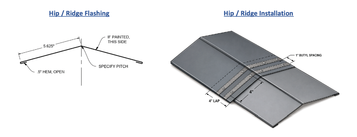
  • Hip/Ridge Installation Checklist:

    Install panels with the required upend detail at the ridge or hip termination. Apply sealant at all exposed corners and panel openings as required.


    Notch the hip or ridge cap as necessary to fit over panel ribs and maintain proper alignment. Use snips or approved cutting tools to create clean, accurate notches.


    Allow the hip or ridge cap to overhang the lower edge a minimum of 1-1/2" unless otherwise specified by project requirements.


    At hips, box and close the lower end of the ridge cap to match the roof angle and provide a finished appearance.


    Overlap successive ridge cap sections a minimum of 2" to 3", working from the lower elevation toward the higher elevation. Apply sealant at all lap joints before fastening.


    Fasten the hip or ridge cap using approved color-matched fasteners, stitch screws, or rivets as required by the application. Fasteners should be installed at each panel rib or as specified in the project details.

hip ridge diagram

VENTED RIDGE DETAILS & DIAGRAM

vented ridge diagram

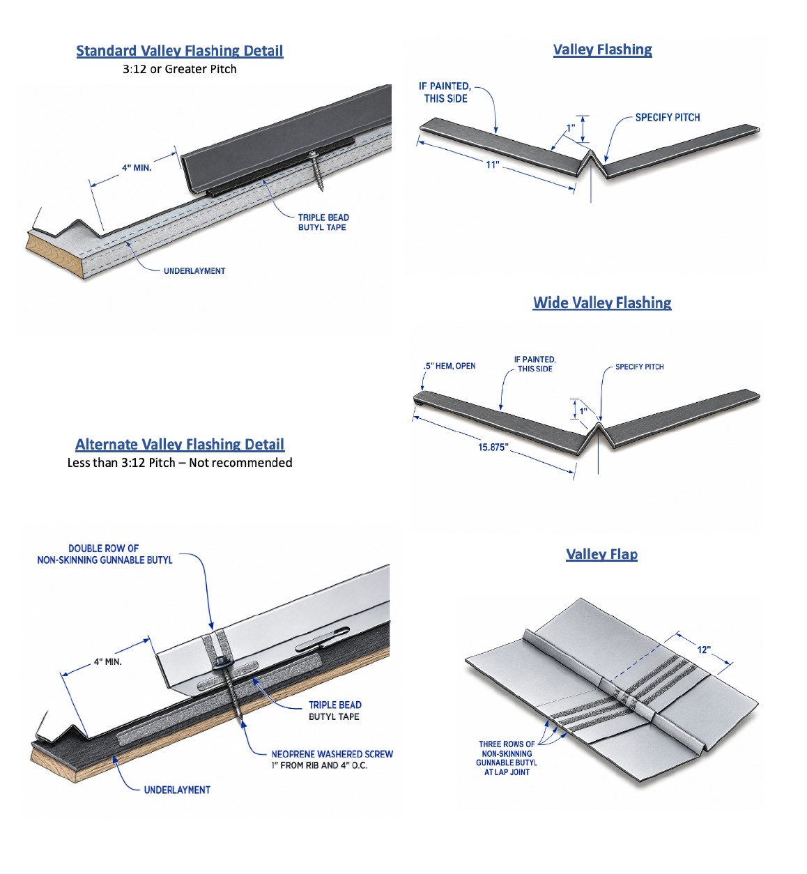
SNAP-LOCK VALLEY FLASHING DETAILS & DIAGRAMS

SNAP-LOCK VALLEY FLASHING DETAILS & DIAGRAMS
  • Hip/Ridge Installation Checklist:

    Secure valley flashing by fastening near the outer hem edge whenever possible. Fasteners should be spaced approximately 18"–24" on center along both sides. Seal all exposed fastener heads with approved sealant.


    When joining valley sections, trim the hem back approximately 6" on each side of the overlapping section. Apply three continuous 1/4" beads of sealant between overlapping valley flashings.


    Extend valley flashing over the ridge where required by project conditions.


    Trim roof panels so they terminate a minimum of 4" from the centerline of the valley.


    Remove all metal burrs and filings from cut panel edges immediately after cutting to help prevent corrosion and surface damage.


    If panel crowning occurs near the valley, back-bend the panel or use an appropriate panel-ending tool to create a downward bend of approximately 30 degrees.


    Apply butyl tape or a continuous 1/4" bead of sealant approximately 1" from the panel edge before installation.


    For wide-valley applications, panel setbacks may be increased based on climate conditions and anticipated water flow. Position butyl tape approximately 1" from the panel end.


    In areas subject to heavy snow loads, wider valley pans and increased clearance from the valley centerline are recommended to improve drainage performance.


    Wide valley flashings should be considered for low-slope roof applications.


    Apply a continuous bead of sealant along the top of valley flashing hems before panel installation.


    Fasten roof panels through the valley fastening flange into the substrate as close to the hemmed edge as practical. Do not install panel fasteners through the water-carrying portion of the valley flashing.

  • IMPORTANT INFO:

    Installation methods may vary based on roof design, panel profile, climate conditions, and applicable building codes. Buyer and installer are solely responsible for verifying proper installation methods. S3 Metals supplies materials only and assumes no responsibility for installation, field measurements, workmanship, or project performance.

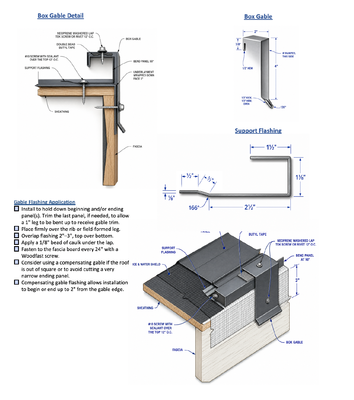
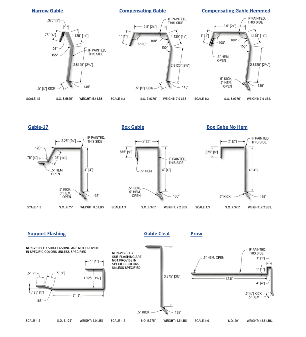
BOX GABLE DETAILS & DIAGRAMS

box gable details and diagram

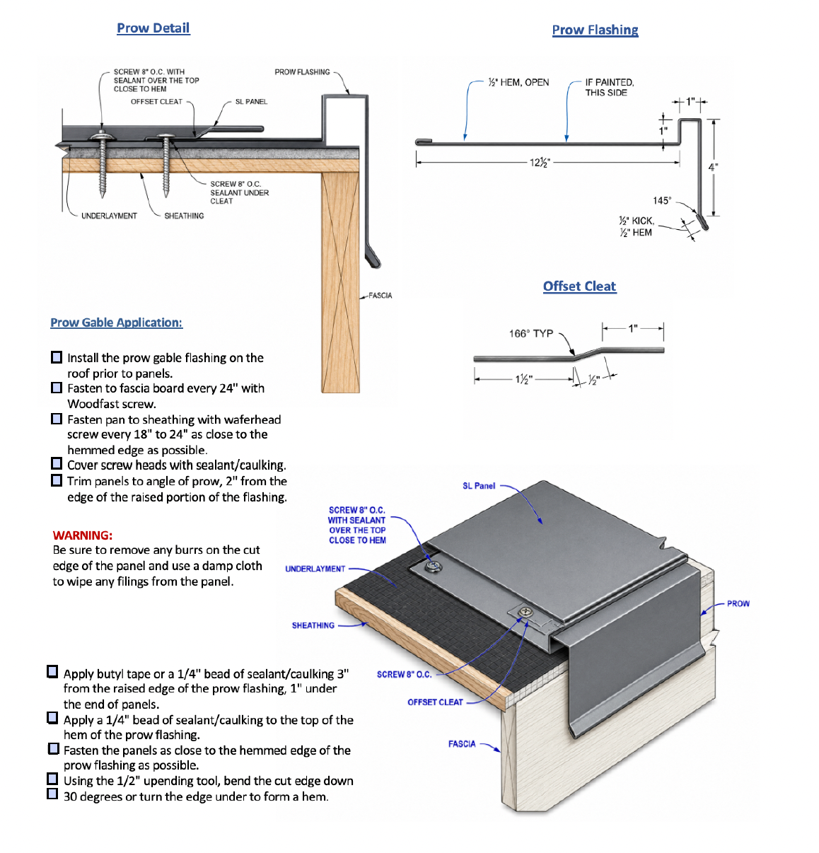
PROW DETAILS & DIAGRAMS

prow details and diagrams

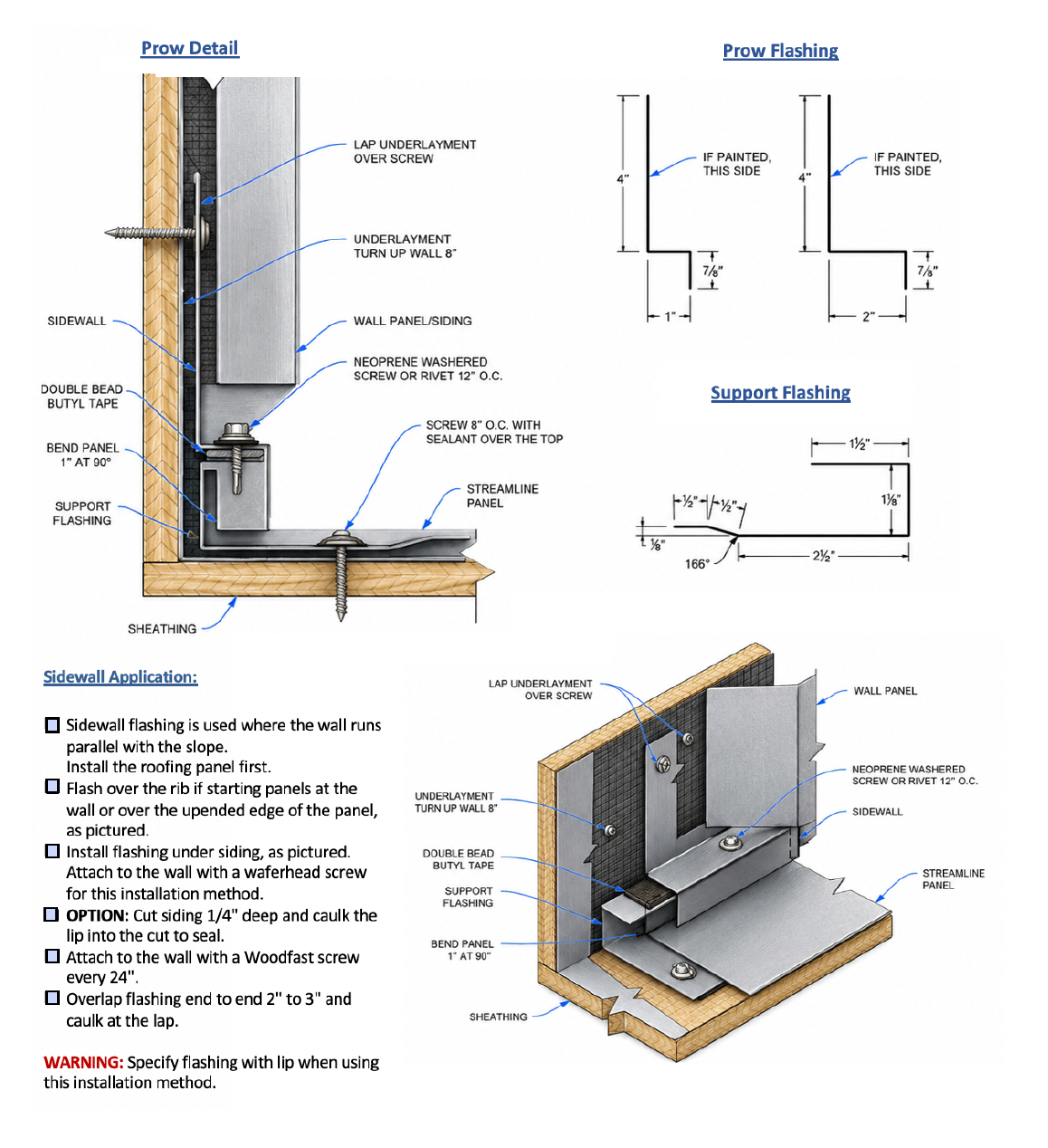
SIDEWALL DETAILS AND DIAGRAMS

sidewall diagram

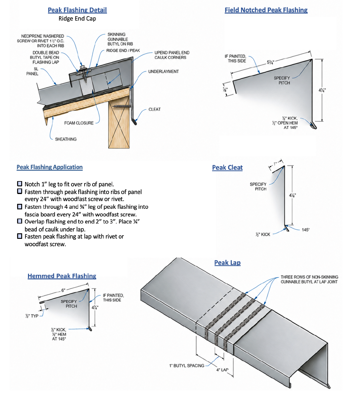
PEAK FLASHING DETAILS & DIAGRAMS

PEAK FLASHING DETAILS & DIAGRAMS

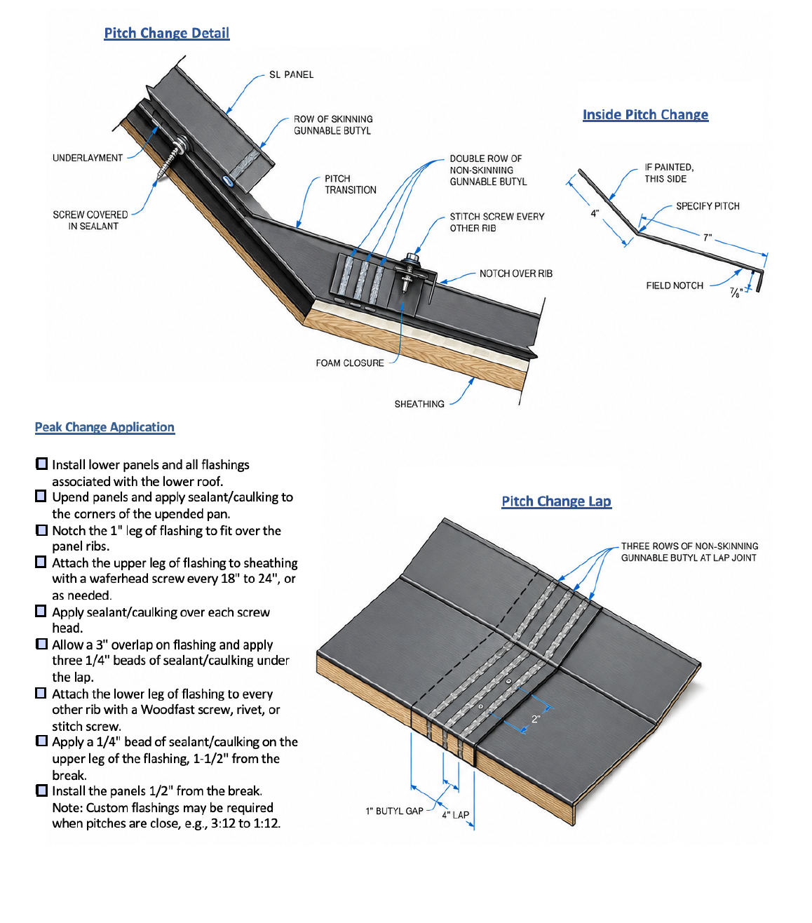
PITCH CHANGE DETAILS & DIAGRAMS

pitch change details and diagram

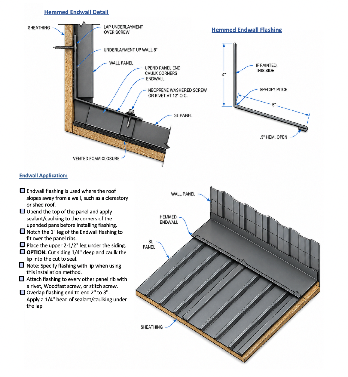
ENDWALL DETAILS & DIAGRAMS

endwall details and diagrams

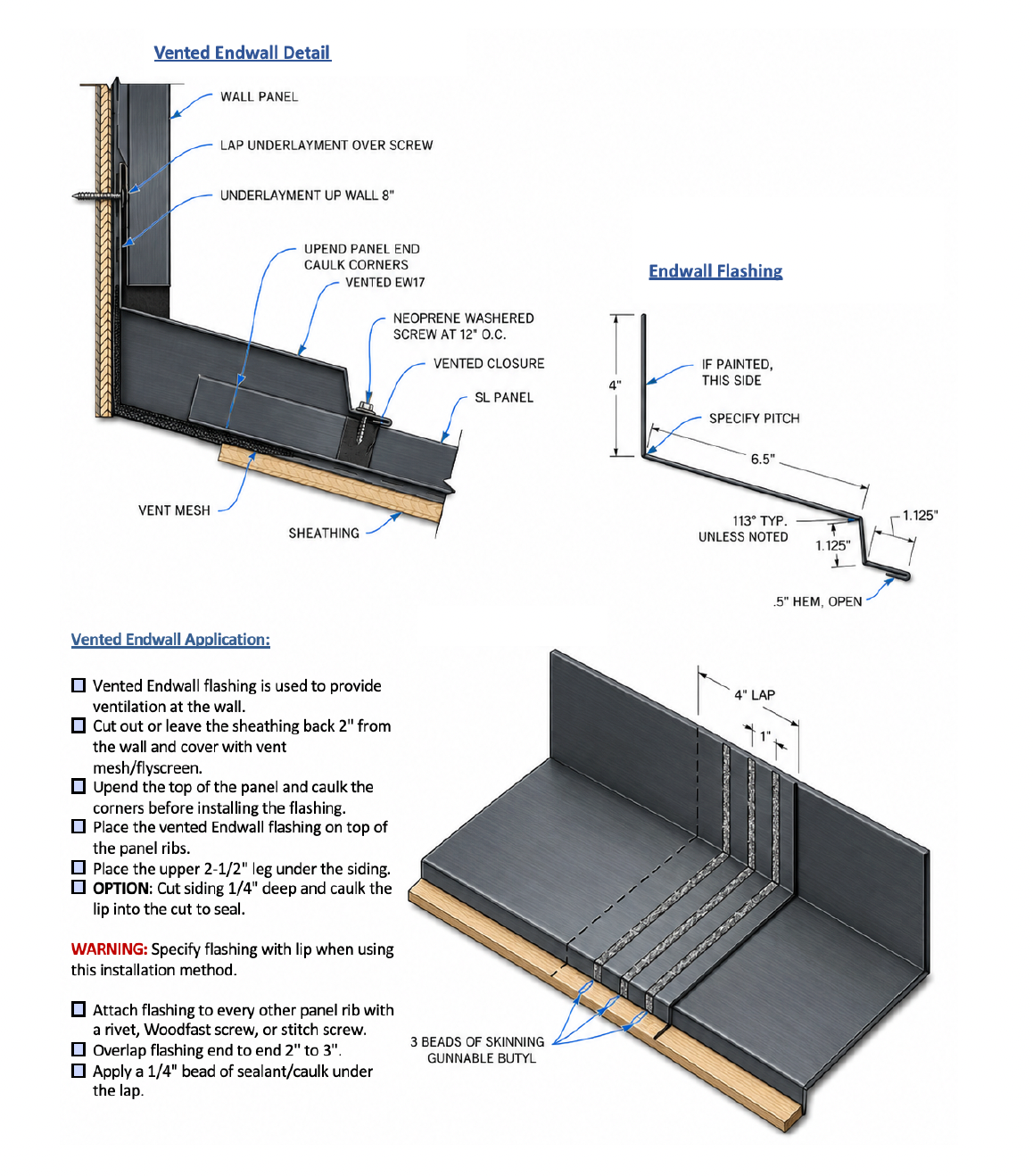
VENTED WALL DETAILS & DIAGRAMS

vented wall details & diagrams

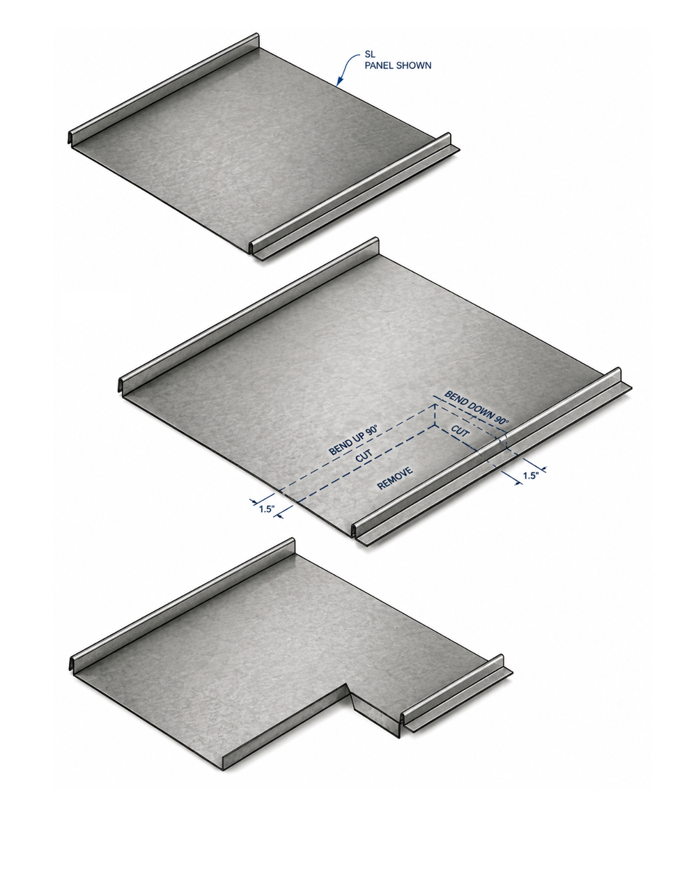
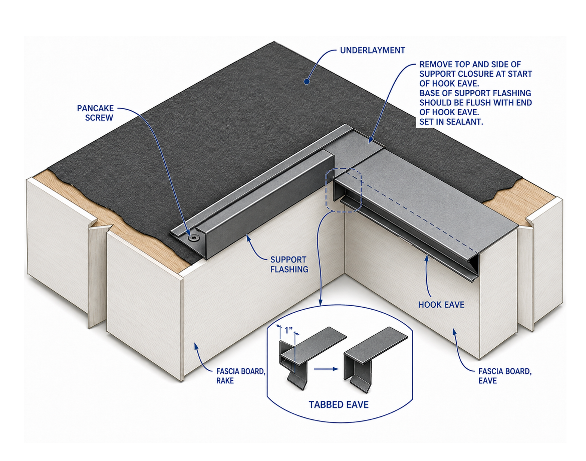
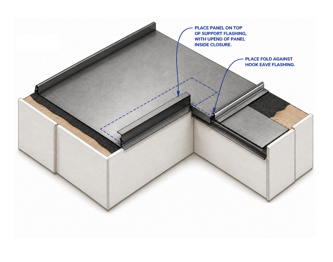
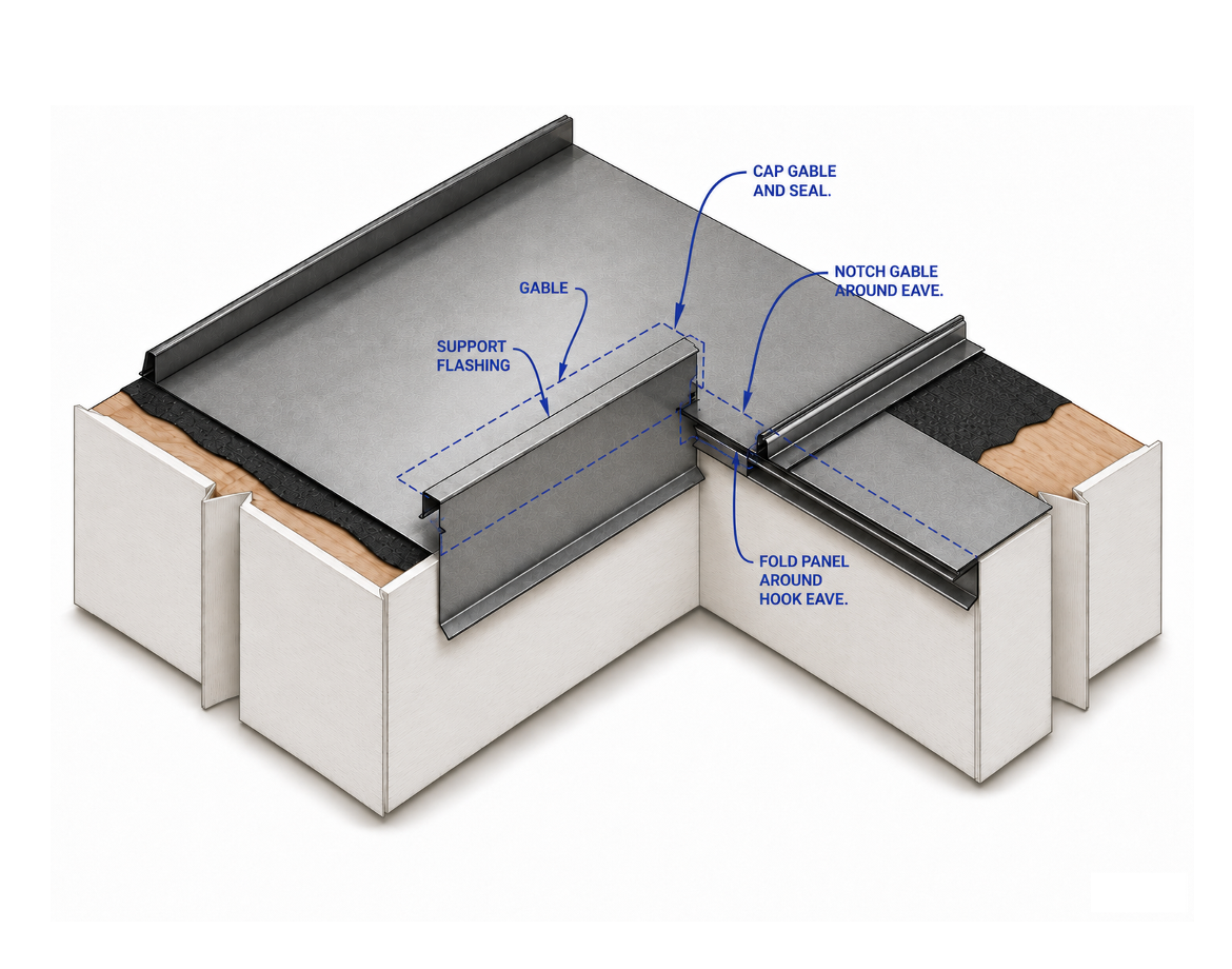
EAVE TO GABLE TRANSITION

vented wall details & diagrams

EAVE TO GABLE TRANSITION STEP 1

eave to gable transition step 1

EAVE TO GABLE TRANSITION STEP 2

eave to gable transition step 2

EAVE TO GABLE TRANSITION STEP 3

eave to gable transition step 3

EAVE TO GABLE TRANSITION STEP 4

eave to gable transition step 4

SKYLIGHT & CHIMNEY DETAILS & DIAGRAMS

Skylight and chimney details and diagrams

SKYLIGHT & CHIMNEY APPLICATION PART 1

Skylight and chimney details part 1
  • Introduction:

    These instructions apply to most standard skylight and chimney installations. Some applications may require custom flashing or additional installation measures. Always confirm the approved flashing requirements with the skylight manufacturer, as deviations may affect the product warranty.


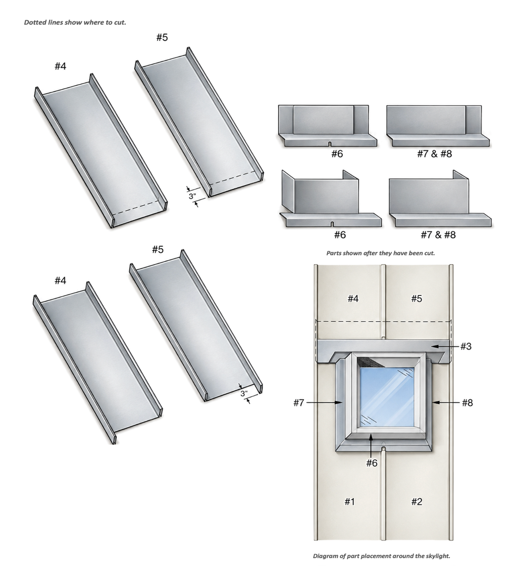
    A cricket may be recommended when water drains toward a curb wider than 24 inches or where debris is likely to collect. Crickets are custom-fabricated to fit the curb or chimney and are installed in place of the head flashing. The installation method for both components is generally the same.


  • Steps 1-3:

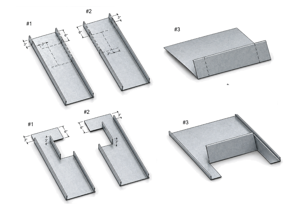
    Step 1: Working from left to right, cut to fit, bend, and install panel #1.


    Step 2: Cut to fit, bend, and install panel Install additional panels as normal between panels #1 and #2, as needed to cover the width of the skylight/chimney opening.


    Step 3: The next piece to install is head flashing #3. First, place a bead of skinning butyl sealant on top of panels #1 and #2 to prevent water from siphoning at the joint.  Next, cut and bend the head flashing to fit. The artificial ribs should be ½" high. Set and fasten the head flashing.


SKYLIGHT & CHIMNEY APPLICATION PART 2

Skylight and chimney details part 2
  • Step 4

    Working from left to right, cut panel #4 to fit, snap it into place, and fasten as normal.

  • Step 5

    Cut panel #5 to fit, install, and fasten as normal. Install additional panels between panels #4 and #5 as needed to cover the width of the skylight or chimney opening.

  • Step 6

    Install bottom flashing #6 using the same method as standard End Wall flashing. Next, install sidewall flashing #7 and #8 along each side of the curb to complete the skylight flashing assembly.

  • CAUTION / WARNING:

    Use skinning butyl sealant at all joints and metal overlaps to help prevent water intrusion. Careful installation and attention to flashing details will directly affect the final appearance and performance of the system.


    The information provided above is intended as a general installation guideline and is not the only acceptable method for flashing a skylight.

SKYLIGHT & CHIMNEY APPLICATION PART 2

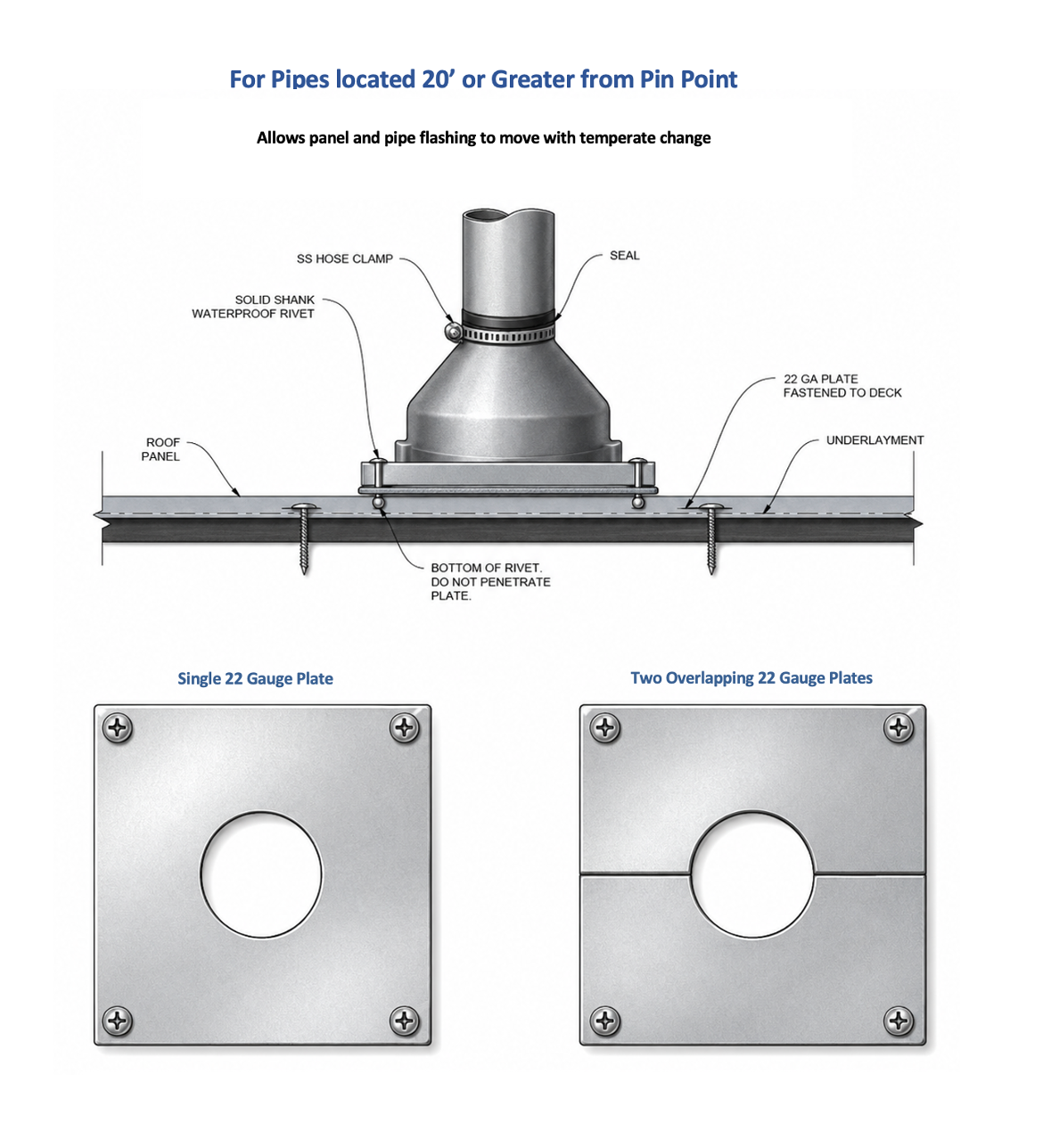
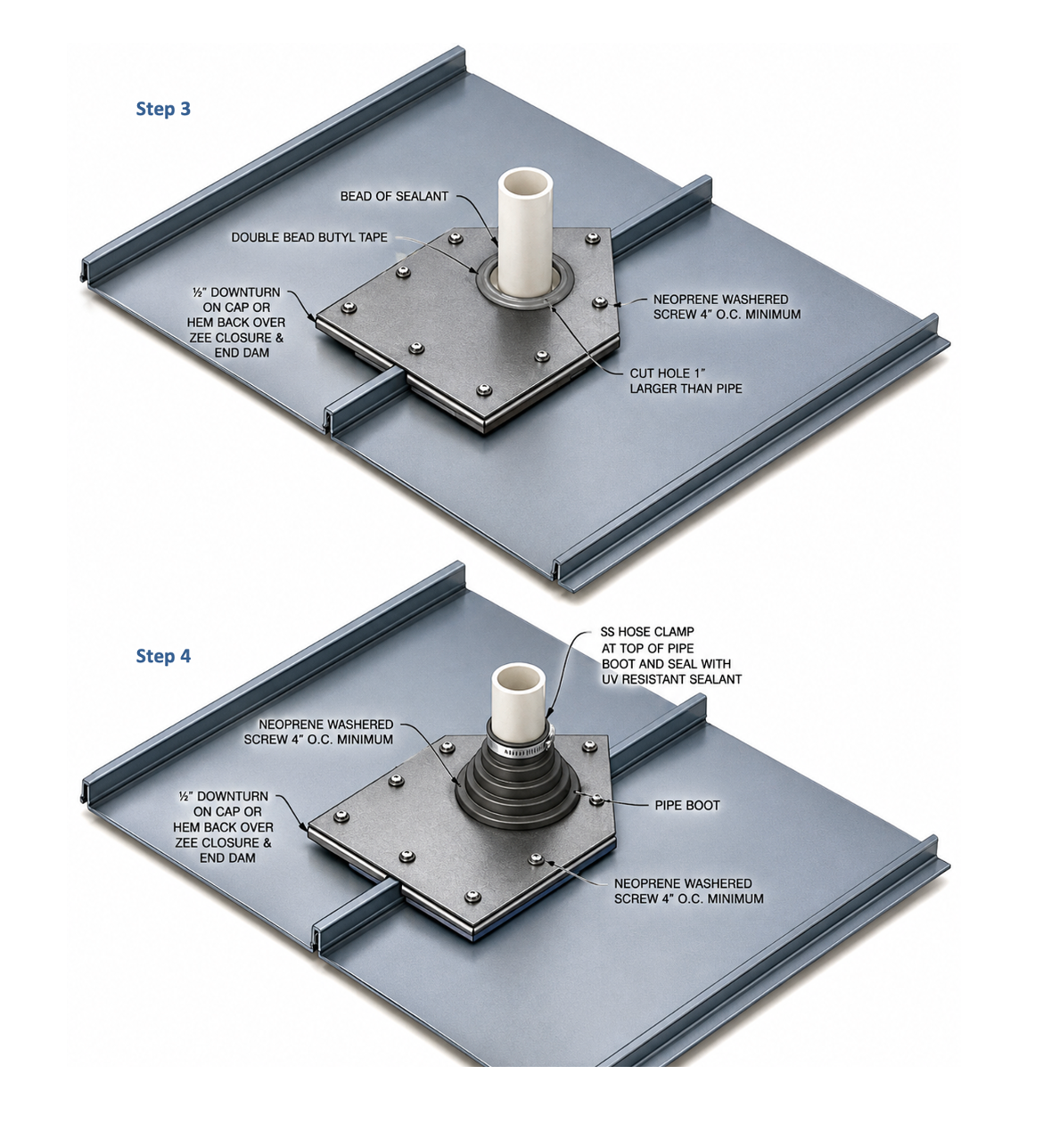
pipe penetration on plate

PIPE PENETRATION ON RIB - STEPS 1 & 2

pipe penetration on rib steps 1 and 2

PIPE PENETRATION ON RIB - STEPS 3 & 4

pipe penetration on rib - steps 3 and 4

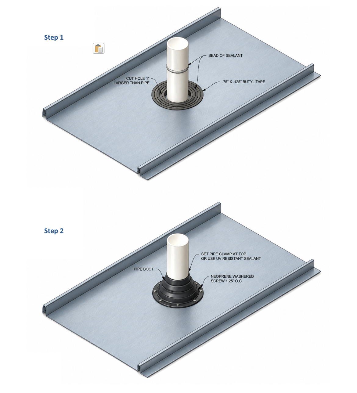
PIPE PENETRATION ON PAN STEPS

PIPE PENETRATION ON PAN STEPS

Snap-Lock Streamline Flash Details

Snap-Lock Streamline Flash Details

Snap-Lock Gable and Prow

Snap-Lock Gable and Prow

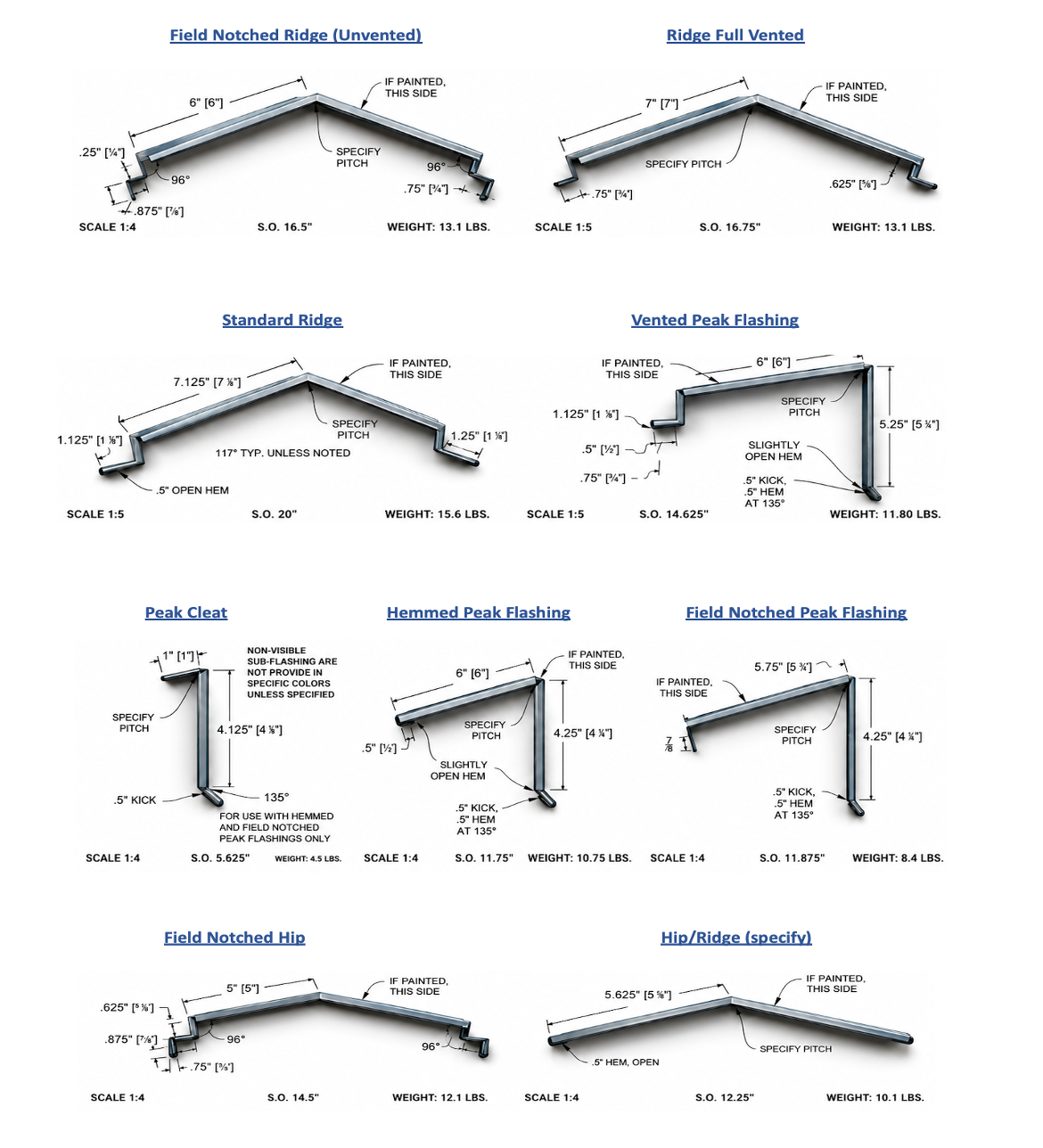
Ridge, Peak, and Hip Specifications

Ridge, Peak, and Hip Specifications

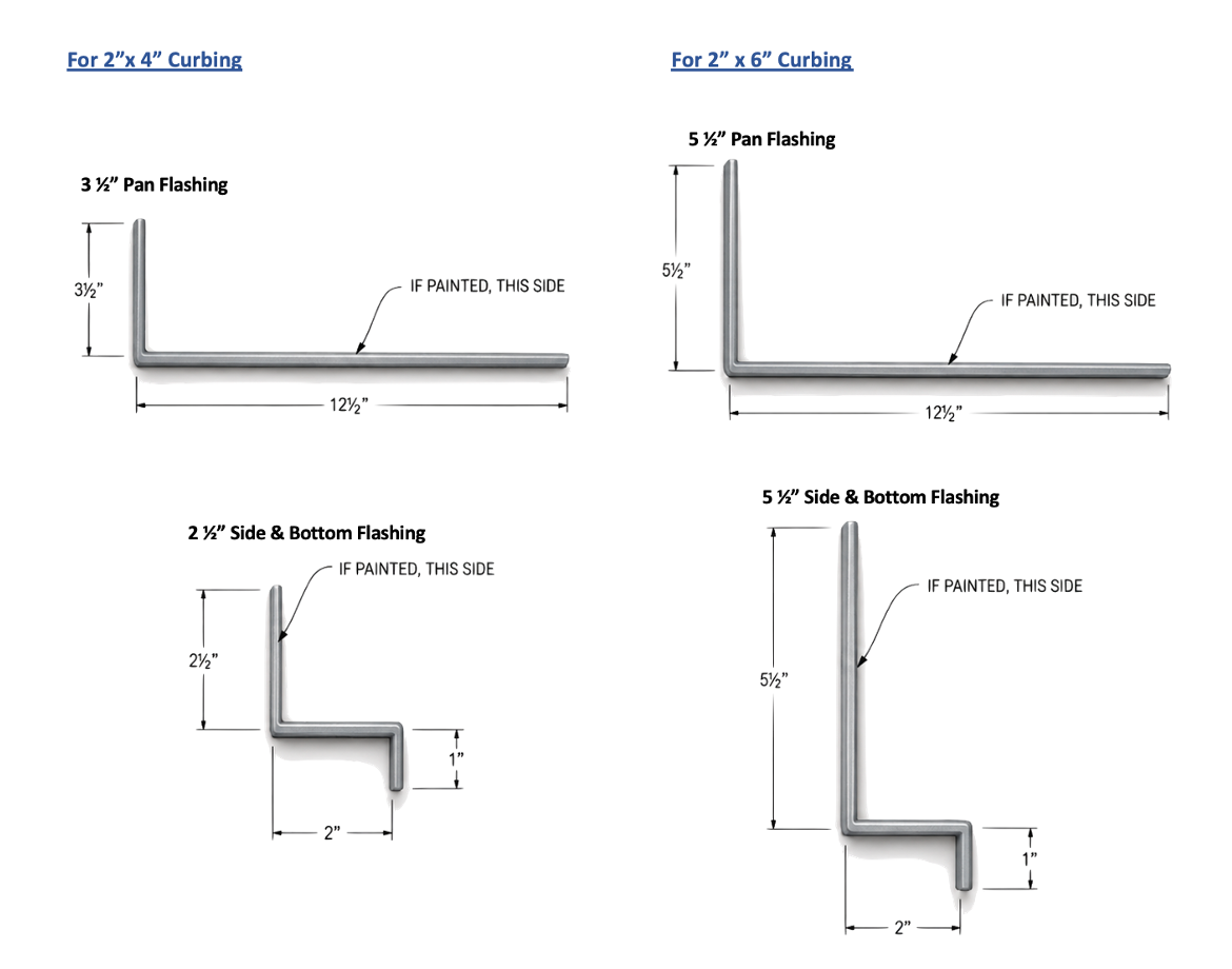
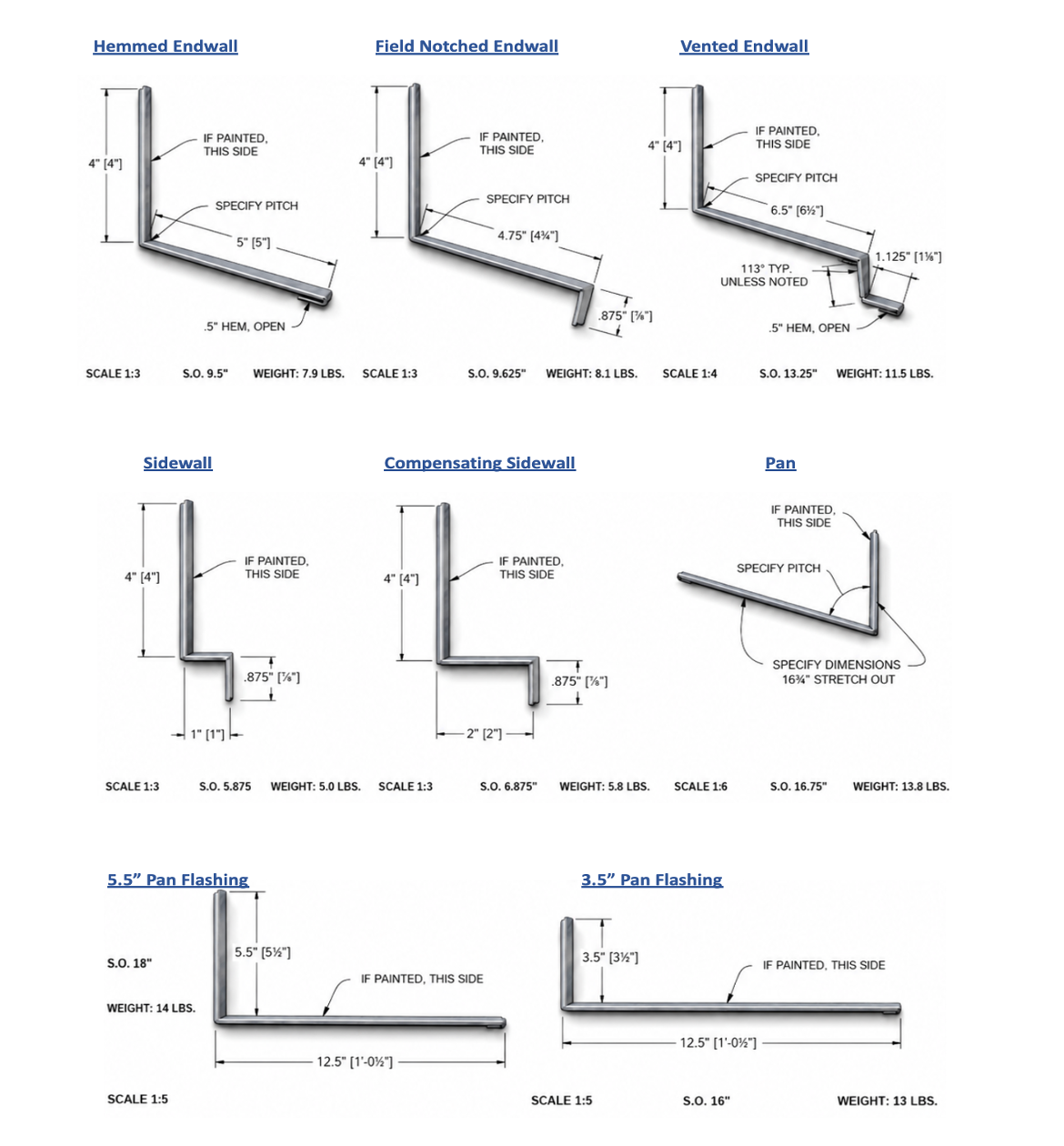
Endwall and Pan Specifications

Endwall and Pan Specifications

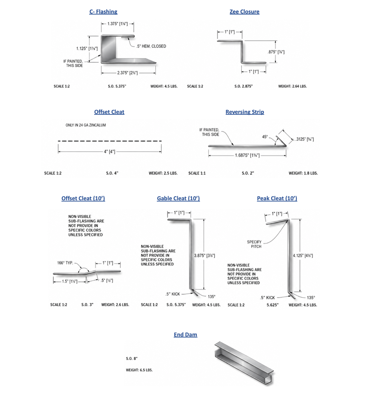
Flashing, Strip, Cleat, and Dam Specifications

Flashing, Strip, Cleat, and Dam Specifications

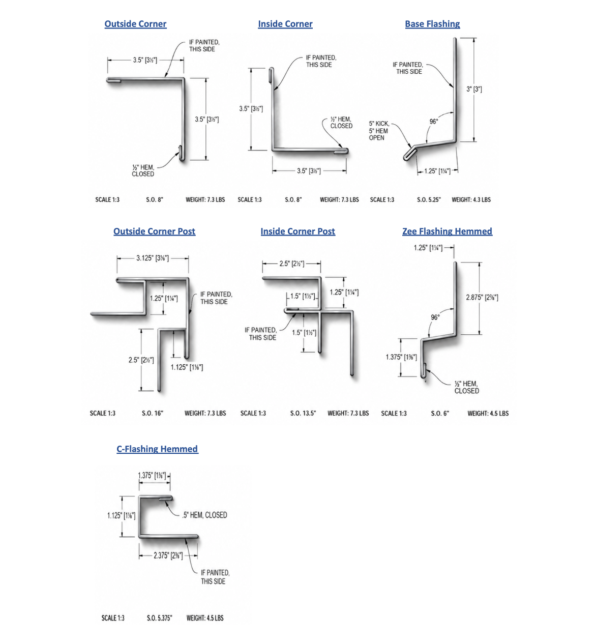
Corner Specifications

Flashing, Strip, Cleat, and Dam Specifications

Please complete the form, and we'll contact you within 24 hours to help guide you through your next project.

Person on a couch using a laptop for a video call in a bright living room

Get a Metal Roofing Consult

Contact us

Coordinated


We work with the homeowner first, or the contractor first, either way S3 provides the materials and cuts you need to install.

In-house


We never outsource anything! From materials to our fleet, packing, unpacking, cutting, and preparation.

As Promised


Our prices, delivery dates, and project times are carefully planned and executed to perfection.

FREE Downloads to help understand Metal Roofing Dubability

Value Description

Right-pointing black arrow icon on a white background

Value Description

Black right-pointing arrow icon on a white background

Value Description

Black right-pointing arrow icon on a white background

Value Description

Right-pointing black arrow icon on a white background

Our Latest News

best metal roof colors,best colors for metal roofs
By Will Schmidt August 6, 2026
Learn how metal roof colors affect energy efficiency, cooling costs, curb appeal, resale value, and long-term performance. Compare SRI, PVDF coatings, California climate recommendations, and more.
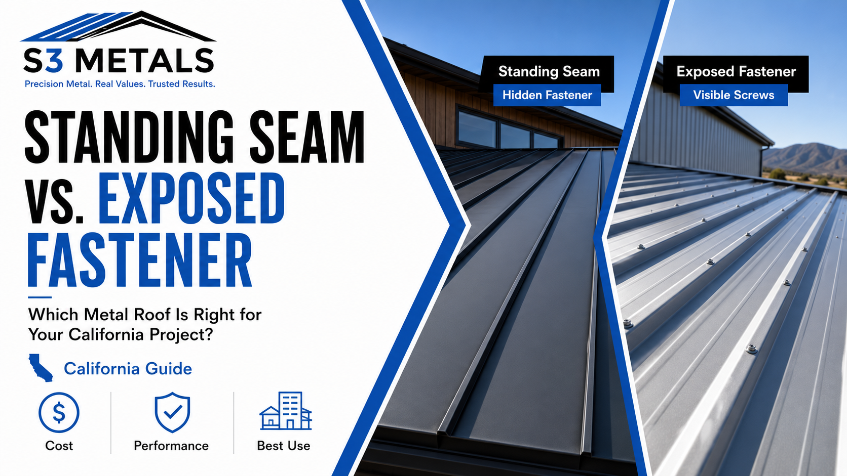
standing seam vs exposed fastener metal roofing
By Will Schmidt July 9, 2026
Compare standing seam vs exposed fastener metal roofing for California projects. Learn cost, pitch, solar, oil canning, coatings, wind, and maintenance.
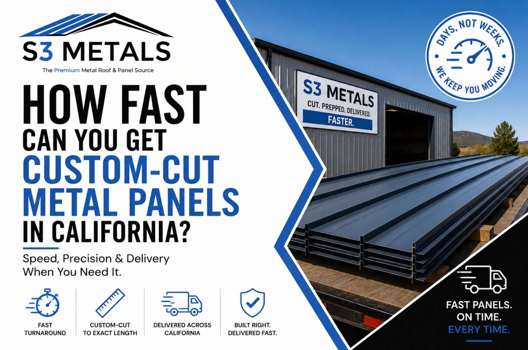
custom‑cut metal panels, California metal roofing lead times, S3 Metals rapid turnaround
By Will Schmidt May 21, 2026
Learn how typical metal‑panel lead times compare with S3 Metals’ rapid turnaround within northern CA for homeowners and contractors.
Blank white banner with a thin black strip at the top and bottom